Power, reliability and real-time computing capabilities are just some of the advantages of using multicore processors. But, careful consideration of safety and certification standards is needed since rigorous testing and validation for critical systems is required by regulation. Our two-part story on the multicore evolution looks at the challenges and benefits of using multicore processors in avionics.
Multicore processors afford some advantages versus single core processors in avionics systems and multicore processors are becoming more common in avionics equipment. In this first of a two-part story on multicore processors in avionics we reached out to industry experts to establish a comparison of multicore versus single core processors, the state of things as to the use of multicore processors in avionics, the difficulties in certification and some solutions available to date.
Multicore vs. Single Core Processors
During the early history of microprocessors, performance improvements and efficiency gains were achieved by continuously increasing the clock speeds of central processing units (CPU), affirms Mike Pyne, senior director of strategic accounts and solutions architect at CoreAVI. “Early processors ran at clock speeds of 10 megahertz compared to today’s processors that run at speeds up to 3 gigahertz. At some point, in the late 1990s it became clear that there were transistor technology limitations associated with ever increasing clock speeds,” he said.
Mike Pyne, CoreAVI
To continue to provide increased performance, multicore processor (MCP) architectures were developed, Pyne observes. “Today, multicore processors can be found in just about every avionics system including mission computers, flight control systems, smart displays, air data processors, navigation gear and of course entertainment hubs,” he affirmed.
Gregory Sikkens, Curtiss-Wright Defence Solutions
Gregory Sikkens, safety critical senior product manager at Curtiss-Wright Defence Solutions, affirms that MCPs are a convenient way to improve performance where an efficient core can be replicated in a System on Chip (SoC). “Not only is this approach convenient, but MCPs can also save space, power, cost and provide an effective solution for integrated modular avionics (IMA) architectures. Today, it is rare to see a true single core processor in new systems as the majority of commercial-off-the-shelf (COTS) devices that avionics equipment depend on typically include more than one processor core,” he said. “For many years, it was the case that all but one core would be disabled on avionics equipment to avoid having to deal with the complications that multicore processors introduced when demonstrating compliance with applicable airworthiness regulations.”
Yemaya Bordain, Daedalean
According to Yemaya Bordain, Daedalean’s president of Americas, the advantages of using multicore processors (MCP) in avionics are the same as for non-avionics applications: higher performance, lower power consumption and improved efficiency. “Some secondary benefits also include their scalability and their ability to execute multiple workloads concurrently. The difference with avionics is our focus on size, weight and power consumption (SWaP), as well as heat dissipation, which is a direct consequence of power consumption and, crucially, certification,” she said.
Roberto Valla, EMEA
According to Roberto Valla, EMEA aerospace and defense head of sales at Wind River, their greater performance allows MCPs to execute multiple tasks simultaneously, which can enable parallel processing of data leading to improved overall performance. “This is particularly important in avionics, where real-time data processing is critical. Another advantage is the increased flexibility and future growth provisioning. MCPs can be configured to support a variety of applications and can provide spare capacity for future growth, making them more flexible than single-core processors and avoiding costly hardware upgrades,” she said. “The increased performance of MCPs can enable multiple applications which previously ran on individual avionics line replaceable units (LRU) to be consolidated onto a common processing LRU using an MCP, reducing requirements for space, weight, power and cabling.”
Andrea Beer, Rapita Systems
Use in Avionics
The use of MCPs in avionics equipment is trending positive, but it is not yet widespread. For safety-critical applications, MCPs were not until recently available as certifiable components and, for higher safety-criticality, such as design assurance level A (DAL-A) flight control systems, few multicore-based systems are yet available, observed Bordain. “For machine-learned systems running neural networks such as those we use, there are no processors currently certifiable that will satisfy our requirements,” she said. “In a white paper we recently co-authored with Intel, we propose a reference design based on the 11th Gen Intel Core i7 and Intel Agilex F-Series FPGA for machine learning applications. This architecture satisfies all requirements for future certifiable machine-learned avionics systems requiring high-performance computing at low SWaP.”
Multicore processors (MCPs) are increasingly being used within avionics systems, they offer increased performance compared to single core processors and allow more functionality to be included within hardware, points out Andrea Beer, marketing manager at Rapita Systems. “They can also contain other embedded functions such as memory management and embedded security, reducing the chip count for a system,” she said. “However, there are numerous implementation and certification issues that are not present in single-core processor implementations and, in addition, the use of single-core processors in so few other industries also raises concerns amongst avionics suppliers over their future supply.”
Over the last couple of years, there have been some successful multicore certifications, with more in development, Sikkens highlights. “In the defence space, most avionics equipment is turning to multicore processing-based solutions as avionics increasingly requires the performance level provided by multicore COTS SoC devices. Overall, multicore architectures are becoming more and more common as understanding increases,” he affirmed. “Also, the availability of tools for multicore processors is also increasing, providing a mechanism to demonstrate that multicore interface channels can account for worst case execution time (WCET) analysis as well as other objectives. I believe that the move to multicore processing in avionics is inevitable.”
The adoption of MCPs is increasing, partly due to the diminishing availability of single core processors, but also because of the increased performance requirements of some modern applications, including those involving artificial intelligence (AI) and machine learning (ML), according to Valla. “MCPs also provide greater processing power and enable consolidation of applications. MCPs are being increasingly used in avionics applications such as primary flight displays (PFD), mission systems, communication systems, and sensor suites, among others,” he said. “Of course, it is important to note that the use of MCPs in safety-related avionics applications is subject to strict safety certification requirements, and their use must undergo rigorous verification to ensure that they meet the required safety and reliability standards.”
Certification Difficulties
The architecture for single core processors is relatively straightforward and the process rigor and certification requirements for qualifying these systems for use in aircraft is very mature, according to Pyne. “MCPs on the other hand introduce a much greater potential for resource conflict which complicates the goal of determinism which is key to endorsing a system for safe flight operations. The European Union Aviation Safety Agency (EASA) and the US Federal Aviation Administration (FAA) have released separate guidelines for the use of MCPs in safety critical applications (i.e., EASA Certification Review and CAST-32A),” he said. “These agencies are now working in concert to finalize these requirements in more formal use of MCPs in avionics applications and address component roles (processor architecture, operating system, drivers, etc.) along with approaches to modelling and testing such systems.”
The main obstacle in certifying avionics equipment with MCPs is ensuring that the system still operates in a deterministic way considering that processes running on each core will be accessing common resources, according to Bordain. “Sharing is always more difficult than keeping things strictly separated. Interference between processors competing for the same resources such as cache, memory, and through shared interconnects, can make it difficult to prove determinism of the system under all circumstances. Some avionics designs utilizing MCPs go so far as to disable all but one core to prevent interference,” she said.
According to Sikkens, at a high level, the obstacle for certification of multicore-based avionics is the need for a deeper understanding of multiple interconnected device details, as well as how software makes use of the hardware. “These requirements add development activities and lifecycle data to the avionics equipment development project,” he said. “MCPs can complicate application implementation and require, for example, an understanding and planning for data-sharing between threads, and the use of shared resources, such as interconnect fabrics and the synchronizing of concurrent operations, just to list a few of the associated challenges.”
Whilst MCPs offer a great deal of advantages, their behavior is harder to verify due to the presence of interference channels, explains Beer. “Interference channels can be caused by a variety of factors, including contention over shared hardware resources. This interference can have a significant effect on timing behaviour, raising critical safety concerns,” she said. “Validating the timing requirements of multicore systems offers new challenges. As traditional worst-case execution time analysis methods do not take interference effects into account, new methods, such as Rapita’s Multicore Timing Analysis Solution have been developed.”
Solutions
While program execution running within a multiple cores enclave is similar to a single core, complications arise when going to an external cores enclave where transfers across the shared internal fabric to shared memory interfaces and interference can occur from each of the cores, observes Sikkens.
“These interference channels can impact performance and can complicate the determination and demonstration of WCET. Also, it can be a challenge to obtain details of the internal fabric to model a WCET determination,” he affirmed. “To help address this challenge, collaboration was formed between avionics equipment suppliers and COTS SoC suppliers, called MultiCore For Avionics (MCFA), which is an ad hoc group that establishes a unified voice of avionics equipment vendors for COTS SoC suppliers that provides guidance for the COTS SoC supplier in preparing common design data artifacts for multicore processor SoCs and assists suppliers in demonstrating compliance with airworthiness regulations.”
There are inherently more possible pathways for interference in MCPs in comparison to single core processors, according to Bordain. “This feature makes it difficult for the software, such as a Real-Time Operating System (RTOS), to control the behavior of the MCP and bound the worst-case execution time (WCET) of tasks being executed,” she said. “These pathways must all be understood, controlled, tested, and validated; therefore, the system design itself should include considerations of interference as well as which features of the MCP are needed for the application. Many MCPs have features embedded to manage resources, such as Intel’s Cache Allocation Technology as part of its Resource Director Technology Framework. We expect this year to see the first product with Daedalean technology certified. Developed out of a partnership between Daedalean and Avidyne Corporation, the Avidyne PilotEye Visual System uses the Intel Core i7 processor, which has four cores.”
Intel’s 11th gen Core i7 processor offers an advantage for aerospace suppliers since Intel has introduced the Airworthiness Evidence Package (Intel AEP), said Bordain. “It provides aircraft-embedded manufacturers with processor artifacts and the tools to analyze and mitigate non-deterministic and unintended behavior to support DO-254 certification up to DAL-A,” she added. “Initially, information was provided in 2016 by the Certification Authorities Software Team in its CAST-32A paper and later that was officially adopted by EASA as an Acceptable Means of Compliance in AMC 20-193. Both regulators recognize the advantages of MCPs and the need to steward their introduction into avionics systems.”
Since their first deployment several decades ago, flight management systems have been constantly updated and they have increased capabilities. In the era of connectivity, flight management systems (FMS) are being upgraded to satisfy this ever greater need. In this feature, we provide an update on how FMS have developed in recent years, the drivers of changes in FMS technology, and what future FMS will feature.
New Features
The flight management system (FMS) portfolio of GE Aerospace is designed for accuracy, connectivity and to optimize flight paths. Continuous improvements to reduce time, fuel consumption and emissions are a constant factor in ongoing development, according to Gary Goz, director of navigation and guidance at GE Aerospace. “Our latest generation FMS, TrueCourse, has a modular design using common components across multiple aircraft platforms while having the ability to tailor modules for a specific aircraft. This creates a development environment that can deliver new and upgraded capabilities to our customers faster than our previous generations,” he says. “Another advancement is in the computing domain.
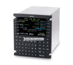
The Universal Avionics UNS-1Ew FMS. Universal Avionics image.
Our legacy platforms support standard keyboard-based ARINC 739 multi-function control and display units (MCDU) driven by the flight management software that runs on a flight management computer (FMC).”
Universal Avionics’ FMS platforms reflect several decades of innovation in FMS technologies and features up to its current UNS-1Ew and UNS-1Fw SBAS/WAAS FMS capabilities, affirmed Dror Yahav, chief executive officer (CEO) of Universal Avionics. “Certified on over 50 aircraft types, we specialize in flight deck upgrades, providing flexible options for aircraft types ranging from the Pilatus PC-12 to the Boeing 747. These products reflect the steady evolutions of FMSs in addressing the navigation and flight management needs of modern aircraft,” he said. “Based on our integrated 12 channel GPS capability, our SBAS-FMSs meet stringent internal monitoring requirements to provide guidance to any of the minimum descent altitude (MDA) levels for area navigation (RNAV) (GPS) approach guidance. They also illustrate the continued integration of FMS with data link enabled features such as push to load supporting a more streamlined working environment; performance, safety, and efficiency, improving the overall pilot experience in the context of FANS 1/A+, CPDLC operations.”
GE Aerospace is currently prototyping a touchscreen control display unit (TCDU) that combines the functionality of the FMC and MCDU into a single, powerful unit with a partitioned operating system, explained Goz. “This is essentially a smart display that also provides an open system architecture that can meet the needs for both civil and military aircraft. Connectivity is also one of the major new features that we have been focused on, and there are two areas of connectivity that are of importance,” he said. “The first is referred to as Connected FMS. This technology essentially creates a secure connection between the FMS and the electronic flight bag (EFB) application of choice allowing data to be exchanged between the two. This requires an update to the FMS, a configuration file that identifies the data to be exchanged, and a software development kit that is used by the EFB application provider to make the secure connection and enable the data exchange. While Connected FMS is particularly suited for the TrueCourse architecture, it has also been demonstrated with GE Aerospace’s legacy 737 FMS and it is an option for all civil and military legacy platforms. Connected FMS can be implemented either through a wired connection or through a wireless connection using an aircraft interface device, such as our SmartDMS.”
GE Aerospace is currently prototyping a new system with a touchscreen control display unit (TCDU) that combines the functionality of the FMC and MCDU into a single unit. GE Aerospace image.
As part of its Connectivity Ecosystem initiatives, Universal Avionics is embedding Connected FMS capabilities in its products, pointed out Yahav. “The Connected FMS delivers pilot workflow improvements based on two-way flight plan sharing, continuous weather and flight performance data exchanges in all phases of flight supported by Universal’s FlightPartner Tablet application. The App ease of use, intuitive interface, helps minimise crew workload, fatigue, and human error working in tandem with FMS capabilities,” he said.
Another feature that is in the early stages of research and development at GE Aerospace is called Cloud FMS, affirmed Goz. “The Cloud FMS prototype has been developed on a NASA project in partnership with SmartSky Networks and Mosaic ATM using the TrueCourse FMS. This is still in the R&D stage but has the potential to bring more connectivity between the FMS and ground-based systems used by air traffic control (ATC) and airline operation centres (AOC),” he said. “The differentiator that Cloud FMS provides gives the ability for the FMS to share data with the receiver, such as modified flight plans, remaining fuel, and weight as examples. This kind of information paired with a digital twin of the FMS, can allow ATC or AOC to perform various ‘what-if’ scenarios to accommodate other traffic, fleet needs, and emergencies with much better results than can be achieved today.”
Drivers of Change
According to Goz, the industry goal of reduced crew workload is a key driver as the FMS is a high workload system requiring a lot of data entry by the pilot. “Automating tasks such that it reduces this workload but keeps the pilot in the loop by allowing them to accept the data provided will be a key first step towards reducing that workload. Connected FMS is a major enabler for this capability, eliminating error-prone manual entry,” he said.
With the advent of the EFB, numerous applications now give the pilot the ability to plan ‘optimal’ routes on their handheld device, Goz pointed out. “However, there is a difference in the calculations that are performed by the EFB applications and those performed by the FMS, this results in differences in what the pilot sees when entering the data to the FMS. The same goes for the calculations that are done by the dispatcher at the AOC. There is no system today that duplicates the FMS outside of the avionics platform,” he said. “Connected FMS and Cloud FMS can help solve this issue by providing actual FMS calculations to ensure the accuracy of the results that other systems compute. These drivers require greater connectivity and/or having a digital twin that can replicate the FMS. This will enable overall greater optimization of the airspace. These types of applications can give a pilot more situational awareness and reduce their workload, especially in high workload situations and thus reduce the time to make decisions in those critical instances.”
The key drivers of changes in FMS technology include interest in increased portability and user interface evolutions, according to Yahav. “This is illustrated by Universal’s i-FMS, a portable FMS with its modular architecture for ready deployment to any ARINC 653 compliant platform and a separate ARINC661 compliant user application and human-machine interface (HMI). The i-FMS is designed as a more opened FMS supporting third-party HMI, customizing of menus and operational logic, as well as integration of proprietary functions by interfacing to the core operating systems,” he said. “Another domain is augmented reality, which couples the FMS with enhanced vision systems capabilities to deliver increased pilot situational awareness in all phases of flight and all weather conditions. As an example, this can include capabilities allowing the pilot to project waypoints and information from the FMS onto the real world, superimposed on our SkyLens head-wearable display (HWD) or a head up display powered by our ClearVision platform.”
The aerospace industry and infrastructure tend to drive and dictate the timeline for major systems like FMS, affirmed Goz. “Depending on if it is for the commercial or military market and the level of technology advancement, it can take anywhere from 8 to 10 years. In the commercial space, there is a lot of collaboration required to make this happen including OEMs, airlines, air traffic control, and regulators,” he said. “There is also the aspect of cost, not just the cost to create the technology, but also the cost of replacing antiquated systems and implementation and integration with other existing systems. Non-embedded avionics technologies such as a Cloud FMS and applications that can run on an EFB that can take advantage of connectivity such as Connected FMS can be developed and introduced at a much quicker pace.”
Future Focus Areas
Looking to the future, a first area of focus, which is considered in the context of Universal Avionics’ Connectivity Ecosystem, is the support for FMS 4D trajectory management along with digital twin technology to cope with ever escalating growth in air traffic and environmental constraint, affirmed Yahav. “Also, support of low RNP (<0.3), A-RNP, and RNP-AR operations is at the focus including enhanced FMS navigation support in particular in degraded/GPS denied navigation environments. In this context, one initiative of ours is currently focused on the DME-DME based navigation,” he said. According to Goz, artificial intelligence (AI) and machine learning (ML) will play an increasing role in avionics and FMS. “Although current FMS implementation does not include any AI/ML, this will play an increasing role in years to come. Early first steps will include non-embedded tools such as decision aids. This will help by bringing together the information needed to make decisions quickly without the need for constant back and forth communication with a dispatcher,” he said. GE Aerospace is developing such an aid that is close to the demonstration stage, stated Goz. “This is a form of situational awareness that will likely be the place where AI will have the most impact in the shortest amount of time and that is because it can help where it is most important in this industry; safety. The more situationally aware a pilot is and the more complete the information is to make decisions from, the more likely that the action taken will conclude in the safest result. We are investing in more AI/ML technologies in the situational awareness space for this reason,” he concluded.
The old saying goes, measure twice, cut once and nowhere is that more important than in aviation and aerospace. Thankfully technology has advanced, making leaps in development and this old saying obsolete.
Aerospace measurement and testing has developed significantly in recent years, and new solutions have been introduced. The aerospace market has also diversified, and there are new players, start-ups and also government-driven organizations investing in the development of state-of-the-art test and measurement technology. In this feature, we have reached out to industry experts to assess the state of the art of aerospace measurement and testing technology, the drivers of change, and what future solutions will be focused on.
State of the Art
According to Manuel Vögtli, who is the head of business development at Kistler, there is a more competitive environment and more budget and benefit sensitivity. “Customers do not automatically choose the highest performing sensors and measuring chains but more and more look for a trade-off between cost and benefit, sometimes ‘good enough’ is good enough. Technologically, we do not see any revolutionary or disruptive developments,” he said. “Applications such as payload and propulsion testing will always play a major role, but the technological limits do expand, for example in terms of temperature. Thanks to our own-grown PiezoStar crystals, we are able to deliver high temperature sensors for environments with more than 1000°C and cryogenic ones for low temperatures down to -196°C and lower.”
Manuel Vögtli, Kistler
Engine fuel consumption has become crucial — both for airline cost savings and also for CO2 and NOx reduction, thus, engine testing during development requires many and very accurate thermocouple measurements, explains Ingo Pletschen, aerospace business development manager at IPETRONIK. “Even optimizations of 0.05% in fuel consumption are important and therefore one needs extremely precise temperature measurements,” he said. “In general, engine and aircraft original equipment manufacturers (OEM) aim for universal data interfaces to ease integration of new data acquisition and test equipment. Even more important is to reduce test cell time by installing the data acquisition (DAQ) to the engine already in the preparation room — so very rugged DAQ is needed.”
PiezoStar is a registered trademark that refers to all crystal types that Kistler grows in-house. PiezoStar crystals offer higher sensitivity and better high-temperature stability than standard quartz crystals. PiezoStar crystals are typically used in sensors for measuring very small forces, i.e., pressure signals or perform measurements at higher temperatures. A PiezoStar sensor can extend the application range in place of commonly used quartz-based pressure sensors Kistler says. Kistler image.
According to François Lachance, product manager at Creaform, traditional measurement techniques have evolved to incorporate more advanced technologies such as 3D scanning, non-destructive testing (NDT) methods, and digital inspection tools. “These developments have improved accuracy, efficiency and data collection capabilities, enabling better quality control and faster decision-making processes,” he said.
Ingo Pletschen, IPETRONIK
For what concerns new solutions, Vögtli affirms that there is a trend towards miniaturization, because mounting space and weight are crucial parameters in aerospace testing. “We recently launched a 6 mm cube triaxial accelerometer which also features a PiezoStar crystal for remarkable temperature stability,” he said. “In addition, we see that piezoelectric force sensors are more and more applied for applications in aircraft testing such as drop tests and landing gear testing where strain gauges were most common before.”
IPETRONIK say jet engine tests require multi-channel measurement technology that is highly precise and reliable, even at extreme ambient temperatures and offers rugged data acquisition solutions. IPETRONIK image.
One thing that is really new is fiber optics, according to Vögtli. “Principally there are two approaches called fiber brag grating (FBG) and fiber segment interferometry (FSI), the newer but more complex FSI is very promising in terms of sampling frequency and resolution, FSI sensors can be used to measure strain, temperature and deformation (shape) in various applications,” he said. “A typical example from aerospace testing is the complex design of helicopter blades. With an FSI shape sensor, digital reconstruction and structural health monitoring can be realized on nanometer level. In addition, FSI sensors complement research and development (R&D) in the areas of ground and flight testing.”
Francois Lachance, Creaform
New solutions in aerospace measurement and testing include high-precision 3D scanners like the ones developed by Creaform, said Lachance. “These scanners can capture detailed geometry and surface information of aircraft components, facilitating reverse engineering, dimensional inspection, and damage evaluation,” he says. “We are always looking for new and innovative solutions to solve industry challenges. The latest addition to our product portfolio is a complete software solution for the assessment of damaged surfaces, VXintegrity. In this platform, we really aim to streamline and improve the way people assess in-service damage, such as dents, with powerful in-house algorithms. By digitizing the approach, the results are easy to communicate between engineers, more repeatable and more traceable.”
Drivers of Change
One of the drivers of changes in aerospace measurement and testing concerns extreme temperature applications, emphasizes Vögtli. “In rocket engine testing, both cryogenic and high temperature accelerometers and pressure sensors are typically required for propulsion testing. And on the other hand, high-temperature sensors are needed as part of the test scope,” he said. “Another driver is the need for piezoresistive pressure sensors which are really small and capable of measuring in high-temperature environments for both static and dynamic pressures.”
According to Lachance, the need for higher accuracy, increased efficiency, and improved collaboration and conformity are driving the changes in aerospace measurement and testing. “The aerospace industry, alike other industries, is seriously affected by the labor shortage and more importantly skilled labor shortage,” he said. “Moreover, the aerospace industry is recovering from COVID-19 and adding pressure to inspection and dimensional demand.”
The HandySCAN 3D is a portable metrology-grade 3D laser offered by Creaform. The company says it is ideal for product development and quality control. Creaform images.
The time it takes for new measurement and testing solutions to be deployed can vary depending on the complexity of the technology and the level of certification required, according to Lachance. “Typically, it can take several years from the initial research and development phase to full-scale deployment. This timeline includes rigorous testing, validation, obtaining necessary certifications if required, alpha and beta tests, and modification of the solution to meet industry requirements,” he said.
Kistler develops base technologies which are then customized to multiple applications for sensor development satisfying specific requirements, explains Vögtli. “Product development can often take several years. However, with our custom product lane (CPL) department, we offer a unique way to deliver customer-specific solutions in a short time,” he said. “The CPL has a team of experts to develop individual products and sensing systems for a given application with end-to-end responsibility from development over production to qualification. This typically includes sensors and systems that do not yet exist. With the help of rapid prototyping and further advanced methodology and processes, we are able to accelerate development processes on demand.”
Future Solutions
For urban air mobility (UAM) and electrical aircraft, new measurement and testing solutions are being researched — especially for electrical power measurements with its high sample rates, but also for capturing new and modern data interfaces, affirms Pletschen.
An important application field is indeed the emerging market for UAVs, drones and eVTOL aircraft, according to Martin Marinák, who is in charge of eVTOL business development at Kistler. “The electrification of aviation comes along with a variety of applications such as propulsion system vibration measurement, battery testing, structural analysis and optimization and electric motor testing, e.g., torque and speed measurement on custom test benches,” he affirmed. “For space testing, propulsion optimization with the trend to liquid fuels is a topic that is currently heavily investigated, just think of ever stronger and reusable rockets, for example.”
There is also much development of new satellites and related testing, like the nanosats, with a weight between 1 and 10 kilograms only that require different components and therefore new test and measurement solutions, affirms Vögtli. “In general, the development and refinement of reaction wheels and cryocoolers is a research area that has continued development year over year,” he said.
Future solutions need to focus on the ongoing trend of big data and digitalization, said Vögtli. “For the digital twin of an aircraft, for example, one needs to conduct several series of real-time measurements with lots of sensors mounted on the unit under test and this of course leads to a vast amount of data to be processed,” he says. “This is why software becomes more and more important: to manage big test data, to process and analyze it reliably and efficiently and to even find hidden patterns and correlations with the help of artificial intelligence (AI) over the long term.”
Indeed, the digitalization of assets will keep being a big trend in the aerospace measurement market, emphasizes Lachance. “When it comes to 3D scanning technologies, our future measurement solutions would likely focus on better integration based on the industry challenges. Future measurement solutions are likely to integrate AI for automated data interpretation, augmented/virtual reality (AR/VR) integration to improve conformity and onboarding experience, and more collaborative tools to ease communication between multiple stakeholders,” he concluded.
Airspace management is on a journey to integrate urban air mobility (UAM) and unmanned aircraft systems (UAS) in the airspace system. Progress is being made in
this domain sustained by a set of main drivers. Mario Pierobon spoke to industry experts to assess the progress made, see what else is needed to proceed with the integration and learn how artificial intelligence (AI) is being used in integrating UAM and UAS into the airspace.
Europe is progressing in the creation of ‘U-space’, the ecosystem that will allow UASs to operate at scale. This has been made possible thanks to a number of factors working in parallel, namely an enabling policy and regulatory framework, a strong, collaborative and inclusive research base and a highly committed industry made up of first-movers ready to deploy, explains Andreas Boschen, executive director of SESAR 3 Joint Undertaking.
Progress So Far
According to Eduardo Garcia, CANSO manager for European ATM coordination and safety, what is currently being faced is a new era for aviation. “The speed of change and rate of innovation will be faster in the next 20 years than they have been in the last decades. To safely accommodate all airspace users in our sky without congestion or increased delay requires new ways of thinking and increased collaboration,” he says. “As we look towards this new future, we can clearly see many opportunities in front of us, but standing in our way are multiple barriers, key challenges that stretch wide across our sector, and extend deep into traditional characteristics that are the by-product of legacy systems and the industry’s prestigious history.”
Andreas Boschen SESAR 3 Joint Undertaking
Detailed technical European Union (EU) rules have been adopted in 2019 to integrate low-and medium-risk drone operations in the airspace, introducing mandatory registration of operators or the need for a risk assessment and authorization for the ‘specific’ category of operations, according to a European Commission (EC) official. “Current drone operations already take place under this harmonized framework. Rules and procedures for the management of drone traffic (U-space) entered into force in January this year and are available to Member States to manage their airspace and allow the safe expansion of drone operations,” the EC official says. “Finally, work is underway to revise the entire aviation regulatory framework to allow the highest risk operations, including the transport of passengers. The first operations of passenger drones, initially with a pilot on board, are planned for 2024.”
Eduardo Garcia CANSO
SESAR research and innovation is allowing U-space to be progressively deployed based on increasing availability of enabling technologies, according to Boschen. “With our recently completed very large-scale demonstrations, we are facilitating the deployment of advanced services, such as detect and avoid, altitude reference measurement, and the interface with manned aviation. Within our SESAR programme, a mature concept of operations (CONOPS) covering UAM has now been developed to show the big picture and maintain coherency. UAM will initially comprise piloted vehicles with unpiloted air taxis expected to come into operation at a later stage,” he says.
Several digital sky demonstrators recently got underway as part of the SESAR research and innovation programme, and more industrial research projects are planned to start later in 2023, according to Boschen. “Together these demonstrators and industrial research projects are offering a real ecosystem with test sites in numerous regions and cities across Europe involving many regional and local authorities, who will ultimately integrate drones into their mobility policy,” he affirms. “Standardization activities are also ongoing, involving all European bodies and in harmony with global bodies; indeed Europe has a UTM Standardization Coordination Group (EUSCG) to define the future standardization requirements and roadmaps.”
Joel Klooster Inmarsat Aviation
According to Joel Klooster, senior vice president of aircraft operations and safety at Inmarsat Aviation, while still in its infancy, the UAM UAS market has evolved rapidly over the last couple of years, and there are some clear goals and milestones the industry is working towards. “With so much innovation on the horizon, it is crucial that key players in the UAV sector work together to meet the regulatory challenges that lie ahead. The U.S. and Europe have published near to mid-term CONOPS with many different flight trials planned or already taking place, which cover various unmanned aircraft systems (UAS) integration scenarios,” he affirms. “However, this testing is still very tightly controlled, typically via waiver, exemption, or by mandating that any newly developed autonomous vehicles must fly in a wholly segregated airspace. End-state integration is managed as safely and efficiently as possible through an ongoing effort to develop standards and regulations for every facet of UAM and advanced air mobility (AAM).
Inmarsat Aviation has designed and developed Velaris, the connectivity service catering specifically for the sector. “Powered by our ELERA global satellite network, Velaris is a global, reliable, and totally scalable connectivity service supporting Command and Control (C2) for UAS. It enables everything from simple tracking and identification for small UAVs to full aero safety services for those operating in controlled airspace. Most critically, it makes it possible for UAVs to be trackable and controllable securely beyond visual line of sight (BVLOS),” says Klooster. “Also paving the way for UAVs to be safely integrated into commercial airspace is the European Space Agency’s (ESA) Iris air traffic management modernization programme, which is powered by Inmarsat satellite services. We provide secure Internet Protocol (IP) connectivity to relieve pressure on near-capacity, congested VHF radio links and deliver high-bandwidth, cost-effective satellite-based data link communications for global air traffic management (ATM) modernization. Together with ESA, we have also invested in the miniaturization of satellite communications terminal technology, allowing almost any class of UAV to be connected BVLOS.”
Drivers and Barriers
Indeed, drones are already being used as everyday tools in an ever-widening range of data-intensive industries, including agriculture, construction, surveillance, filming, healthcare, emergency medical services, energy, the environment, public safety, and security, points out the EC official. “In the future, drones could also be used as platforms for communication hubs, for weather and pollution monitoring, and for the maintenance of renewable energy installations, particularly offshore wind farms,” the EC official affirms. “In general, they offer a faster, more flexible and more economical and/or safer alternative to other modes of transport, such as helicopters. Further progress in the integration of drones into the airspace will require additional work on the Single European Sky rules to take into account the differences between the navigational performance of manned and unmanned aircraft.”
The key driver behind the progress so far in Europe has been industry expressing a clear and pressing business need and the European Commission putting in place a comprehensive and enabling policy framework in a timely manner, according to Boschen. “Added to that is the strong cooperation with the aforementioned standardization and certification bodies and the full inclusion of all stakeholders in the building of the U-space drone ecosystem,” he says. “In our area of research and innovation alone, we have succeeded in bringing on board all the relevant stakeholders, including cities and civic authorities, as well as emergency services and airports. This exposes lessons and experience not evident from sand-boxed research,” he says.
The true driver of industry change has been the ‘industry’ itself, namely the designers and manufacturers of new, primarily electric vertical takeoff and landing (eVTOL) aircraft, and traditional airlines who see an opportunity to expand their services to connect passengers door-to-door, explains Klooster. “The vehicles are here; several are almost certified and ready to fly while many more are in late design/early testing phases. The business cases are also solid, with many major market contenders working to advance progress,” he says.
As the drone services market continues to take shape in Europe, pressure is on to make sure that these air vehicles are safely and securely integrated into an already busy airspace, according to Garcia. “Transforming infrastructure and services to support such operations is critical to harnessing the potential of the sector, unlocking market growth, jobs and services for EU citizens,” he says. “However, a simple adaptation of the current air traffic management system is not enough; accommodating these air vehicles in the numbers forecasted requires a new approach. Citizens’ confidence and acceptance will be critical to the further development of the drone services market.”
The hope is that drone management and integration will ultimately allow for a large series of operations in harmony with the current ATM system.
Indeed, public perception of the UAV industry is mixed, points out Klooster. “As to the safety, cybersecurity and the environmental impact of UAVs, public opinion is beginning to shift as the number of use cases showing how UAVs can be used in critical scenarios is increasing, such as vaccine delivery to remote areas, rescue missions to save lives, and drone use in risky surveillance or remote inspection situation,” he says. “To increase awareness of UAV capabilities, in July 2022 Inmarsat announced a global partnership with Flight Crowd – a collaboration designed to improve engagement and understanding across the air mobility and aviation sectors, the public and the government. Through a series of collaborative outreach projects, we set out to showcase the wide-ranging benefits of this new industry, highlighting the capabilities of UAM and how it can support the mobility of people, goods and services while encouraging communities to have a say in the future of the flight industry themselves.”
According to Boschen, one obstacle is the terminology used to describe what is being done in the UAM/UAS domain. “Even now, stakeholders use terms differently, for example terms relating to altitude and height, separation, separation standards and minima, surveillance, tracking and so on,” he says. “Standardizing all these terms, and driving a common approach to performance requirements, will be essential going forward. This is something SESAR has placed a lot of emphasis on in the CONOPS. Before UAM can be contemplated, further work will also be needed on defining the flight rules, as well as certification and standardization for safe separation.”
One thing which is limiting progress in the industry is the delay in advancing current aviation regulations to accommodate the necessary changes to support the integration, observes Klooster. “Changing regulations is a very long and laborious process, primarily due to the fact that the existing airspace system is complicated, and not because there is a lack of desire for collaboration in the industry. Industry and regulators must work together to safely allow for the integration of a huge number of new aircraft types with varying capabilities, flight characteristics and operational purposes, while continuing to ensure the airspace remains accessible and efficient for existing users who are flying today,” he says. “In addition, key players must ensure that rules are aligned internationally so that new UAM operators do not have to adopt different equipment or procedures in each country they intend to operate in.”
Indeed, the integration of drones remains a complex issue and there are still areas to be addressed to ensure the effective implementation of U-Space in Europe, affirms Garcia. “This includes clarity on the responsibilities of actors within the system and how to facilitate interoperability and the integration of operations. Practical aspects of implementation and the electronic transparency of all airspace users must also be addressed,” he says.
Specific Requirements
U-space requires a high level of digitalization and automation of functions in order to support more complex operations, such as assistance for conflict detection and automated detect and avoid functionalities, explains Boschen. “The aim is to achieve automated drone management and integration, allowing for a large series of operations, many of them even simultaneous, and all of this in harmonious coexistence with the current ATM system. These requirements are coming from the drone industry and the wider aviation ecosystem through use cases and are integrated into our programme for further research and operational testing through established channels, such as the European ATM Master Plan,” he affirms. “They are also being fed into regulatory and standardization processes on U-space and UAM, and there are regular changes on these needs in fora such as the European Network of U-space Demonstrators.”
BUBBLES is a project targeting the formulation and validation of a concept of separation management for UAS in the U-space. SESAR image.
Drone technologies and use cases are evolving rapidly, with new products coming to market at an increasing pace that also cover a wide range of operations, from very low to high risk, the EC official highlights. “This is why the EU, in consultation with industry, has adopted a risk-based, operation-centric regulatory framework, which is regularly reviewed and improved to keep pace with this innovative sector,” the EC official says. “As this framework is performance-based, it is necessary to encourage faster development of technical and safety standards by all stakeholders to ensure that the pace of innovation in the drone industry can be maintained.”
In addition to the design and certification requirements for vehicles and operators, UAM operators will need supporting infrastructure within urban areas, according to Klooster. “This includes vertiports or multimodal transportation hubs, refuelling and recharging capabilities, a command, control and communications link to their vehicles, and a clear, agreed set of operating rules understood by all users of the airspace,” he says. “Requirements are currently being devised by aviation standards development organizations and government agencies, and also discussed across a variety of industry forums and local planning and community outreach efforts.”
According to Garcia, in order to attract the right talent in the future, it is necessary to revolutionize training capabilities, reduce certification timelines and invest in change management processes. “All stakeholders need to jointly work to create a global traffic management integration roadmap, including a pathway to AAM to plot a course toward full convergence of ATM and unmanned aircraft systems traffic management (UTM), and establish a network/ecosystem of aviation modelling and simulation tools and sandboxes to test, trial and demonstrate new forms of service provision,” he says.
Artificial Intelligence
Looking to the future, artificial intelligence (AI) has huge potential for supporting the integration of UAM and UAS, Boschen points out. “Given the forecast number of vehicles and operations, there is a real need to automate aspects of managing the airspace and the traffic. BUBBLES, a recently completed SESAR project, developed a concept of operations for separation management where applicable separation minima are dynamically updated using AI-based algorithms to adapt them to the actual performance of communication, navigation and surveillance (CNS) systems,” he says.
Another project, USEPE, investigated the use of machine learning (ML) algorithms serving multiple purposes, for example to help identify in advance conflicts using a recurrent neural network (RNN) algorithm, explains Boschen. “The developed ML engine provides an automated quantitative assessment of separation management. However, the use of AI is a relatively new domain for air traffic management and therefore more work will be needed on the trust framework and certification of these advanced decision-making tools,” he says.
The expansion of UAS operations will require the automation of a number of functions related to flight and traffic management, observes the EC official. “These areas are likely to benefit from the application of AI and ML technologies, which use data to train algorithms to improve their performance. This is still a dynamic area of research, but one for which the European Union Aviation Safety Agency (EASA) is already studying and developing guidance,” says the EC official.
The integration of flying taxis in a safe manner into the airspace system with a combination of autonomous and crewed operations raises considerations such as air traffic controller workload, communication delays, emergency management, voice-to-text technology, mixed equipage operation, and uncooperative aircraft, according to Garcia. “Legacy air traffic management systems were not designed for the automated aircraft of tomorrow. In the future UAM environment human intervention and coordination will be the exception, not the norm,” he affirms. “Automation will support a high level of safety, security, capacity, and scalability, while extending the capabilities of people. Establishing new, desirable, and legitimate roles for personnel that complements an automated, intelligent, data-powered system is key to the evolution of the aviation sector and its talent.”
AI and ML will significantly impact drones and UTM integration in urban low-level airspace, leading to higher levels of automation and safe operation, according to Garcia. “AI will be developed and used by USSPs and UAS operators, but regulated to ensure a legal framework that balances safety and citizen rights,” he concludes.
High speed cameras are used to capture pictures of very rapid events that would be impossible to capture with normal cameras. As such, they are extensively used also for aerospace testing purposes. Industry experts assess the use of high speed cameras in the domain of aerospace testing, the specific requirements of the aerospace industry with regard to high speed cameras, the factors to consider when selecting a high speed camera and artificial intelligence as an area of integration.
Aerospace Testing
A typical flight test instrumentation high speed camera is capable of taking images at speeds of 200 frames per second or higher and these are collected using a global shutter, which means that the entire image is captured at the same moment in time, affirms Ben Kupferschmidt, senior product line manager for network and ground solutions at Curtiss-Wright Defense Solutions. “The result is a clear image without motion blur, despite the very short exposure time. High speed camera imagery can then be played back at slow speeds to allow engineers to perform data analysis on complex events involving rapid motion,” he says. “In the aerospace industry, high speed cameras are useful for a number of flight test instrumentation (FTI) applications. High speed cameras can also help with confirming proper operation for any complex moving surfaces on the aircraft, for example aerial refuelling and de-icing systems. By using multiple high speed cameras, it is possible to capture multiple angles of the same event. The imagery data from these different angles can be combined to help generate a 3D model of the target event.”
High speed cameras are capable of capturing super-fast events by recording thousands, or even millions of frames per second, affirm Anders Kalldahl and James Engel of Phantom Ametek. “Most events are in the millisecond or microsecond range in duration; indeed, we sometimes refer to high speed cameras as ‘time microscopes’. A traditional microscope enlarges objects too small to be seen by the naked eye, while a high speed camera expands the time of an event that is too fast for the naked eye and the brain to process,” they say. “In the aerospace industry, high speed cameras are commonly used in high speed wind tunnels for aerodynamics and shockwave studies, component stress and performance testing using techniques such as digital image correlation (DIC), flow visualization through particle image velocimetry (PIV), in-flight stores release testing, and rocket motor testing.”
Rob Huculak and Daniel Castillo of the National Institute for Aviation Research (NIAR) at Wichita State University affirm that high speed cameras provide valuable information from a wide range of experimental tests in the aerospace industry. “They capture, at large frame rates, fast-paced events, allowing test engineers to have clear exploitable visuals. This provides insight at the microsecond scale on how deformations take place, how velocities change, or failures occur during dynamic events,” they affirm. “A major benefit comes from advanced photogrammetry software which enables the direct measurement of displacements of test objects in a high speed test; this software requires a calibration to be done for each camera, lens, and focus setting. It corrects for parallax, perspective, depth, and scale factor in order to output the correct displacement, for example that of an occupant kinematics in seat testing. One of the most advanced areas where high speed cameras are used is DIC where a pair of cameras is calibrated and the test images are analysed simultaneously to determine the 3D coordinates and displacements of the object of interest.”
Rob Huculak NIAR
These Sick Ranger cameras, similar to one used in the NIAR labs, offers fast 3D measurement at high speed at sensor resolutions of up to 1,536 pixels in 3D and 3,072 pixels in grayscale and color. The company also says the camera is flexible in configuration, working distance, and field of view. It also has a multiScan function for simultaneously measuring 3D shape, contrast, color and scatter. Sick image.
In the aerospace industry, high speed cameras are used for the research and development of engines (spray and combustion), materials (to improve strength, to develop new materials, to lighten weight), welding (optimizing the welding method), and visualizing high speed mechanical structures, affirms Alex Kiendl of MESSRING, a distributor for nac cameras for the European and Indian market. “Cameras are used not only for visualization but also for analysis by using various image processing technologies, such as two-color method/two-color ratio method for temperature analysis, DIC (for deformation measurement), PIV (for flow measurement), the Shlieren method (for visualizing air density change), and motion analysis,” he says.
Jerry Beeney, Teledyne FLIR
High speed cameras can also be coupled to thermal imaging. Thermal imaging cameras convert infrared radiation into a visual image that depicts temperature variations across an object or scene; this allows the cameras to make non-contact measurements of an object’s temperature for data acquisition, analysis and reporting, according to Jerry Beeney, director of global business development at Teledyne FLIR. “The process of using an infrared camera for data viewing, recording, analysis and reporting is often referred to as ‘thermography’,” he affirms. “High speed thermal cameras often refer to cameras which can achieve frame rates in excess of 100 frames per second, with some being able to reach maximum frame rates of greater than 50,000 frames per second. This allows the cameras to accurately measure temperatures of fast thermal transients and moving targets.”
Curtiss-Wright’s nHSC-31-S1 series camera is a stand-alone and/or networked high speed camera that is capable of operating at 500 frames per second. The camera includes an integrated CompactFlash recorder to allow easy removal of critical post-test data. It also provides integrated video preview and integrates into a system with other TTC network equipment including switches, recorders and the nMGR-2000-1 high speed camera manager. The camera is configured using special software and the images that are stored in the camera’s memory are transferred to a PC and converted to industry standard image formats. Curtiss-Wright images.
High speed thermal cameras are routinely used in the research, development and testing phases within all sectors of the aerospace industry to verify and improve the thermal performance of critical aviation electronics, points out Beeney. “When mated with the appropriate microscope lenses, high speed thermal cameras can detect small thermal anomalies in individual components of integrated circuits. They are also used in material testing to detect potential defects in critical components in airframes and propulsion systems,” he says. “These non-destructive testing (NDT) processes usually involve active thermography techniques where an excitation source creates a thermal difference which the thermal imaging camera can detect and evaluate for potential weaknesses or deficiencies.”
Specific Requirements
The range of applications within the aerospace industry is quite broad, and so are the specific requirements of the aviation industry about high speed cameras. “Taking NIAR AVET as an example, we possess several high speed cameras with a maximum frame rate of 2,000 frames per second and few more cameras capable of going as high as 480,000 frames per second,” say Huculak and Castillo. “Due to the nature of the aerospace industry, there is constant push towards maximizing the quality and amount of information gathered for any given test. Hence, manufacturers are continuously looking to improve the capabilities of their equipment catalog.”
According to Kupferschmidt, the aviation industry needs high speed cameras that are rugged and capable of surviving the extreme environments in which aerospace vehicles operate. These requirements include the need to function across large temperature ranges and high G-forces, and the cameras also need to be relatively small, low power, and capable of operating autonomously. “Ideally, the cameras should be triggered automatically when the target event happens. This ensures that the timing is correct, since a key limitation of high speed cameras is the fact that they have a limited amount of internal storage for images,” he says.
Ben Kupferschmidt Curtiss-Wright Defense Solutions
Multiple cameras are typically mounted at different locations on board the aircraft, providing different fields of view of the target event, observes Kupferschmidt. “In order to combine the images from multiple cameras into a single model for data analysis, it is vital that the time on each camera is in sync. This enables the engineers to be confident that the images from different cameras are aligned in time,” he affirms. “Requirements for high speed camera applications are sent to high speed camera manufacturers using the normal request for proposal process. Most customers are looking for a commercial off-the-shelf (COTS) solution that has the flexibility to accommodate their unique needs.”
Kalldahl and Engel affirm that the specific requirements of the aviation industry include frame rates from 1000 frames per second to 75,000 frames per second at a minimum of 1-megapixel resolution, and in the case of DIC testing, 4-megapixel sensors are required for best results. Furthermore, many tests are performed with less-than-optimal lighting conditions so sensors with high sensitivity to the available light are needed. “This high sensitivity is especially important since low exposure times (fast shutter speeds) are usually required to eliminate motion blur,” they say. “These requirements are usually communicated through a meeting with the test engineers and an on-site visit to evaluate the test parameters and environmental conditions in order to match their specific requirements to a particular camera model. Years of experience with aerospace testing has led to sensor development that addresses the specific needs of aerospace test engineers.”
High speed thermal cameras are continuing to improve in both pixel resolution and maximum frame rates, according to Beeney. “The aviation industry in particular is interested in higher pixel resolutions at higher frame rates since it can help them to get more measurement pixels on the article being tested at high frame rates,” he affirms. “The increase in pixel density on the measurement target improves the accuracy of the non-contact temperature measurement while also providing a more detailed understanding of the thermal gradients on objects of interest. The aviation industry also requires high speed thermal cameras to utilize industry standard connections and protocols for data and camera control.”
Decision Making Factors
There are many factors that go into selecting a high speed camera. According to Kupferschmidt, the most critical initial decision is to determine the required frame rate and resolution for the images. He specifies that most aerospace flight test instrumentation applications need between 200 and 500 frames per second and that the customers typically want a camera resolution of 1280×1024. “Other key factors include the size, weight and power requirements for the specific test. In particular, high speed cameras often have to fit in tight spaces on board the test aircraft,” he says. “Another key factor to consider is the triggering method for the high speed camera. Ideally, aerospace customers seek flexibility in their cameras that support multiple options for triggering. The overall system architecture and system integration is vital to a successful high speed camera test; customers want a fully integrated system where all of the different pieces work together seamlessly.”
Among the factors that should be assessed when deciding the type of high speed camera to buy, there must be always a balance between required frame rate versus resolution, minimum shutter speed/available light versus sensor sensitivity and record time, according to Kalldahl and Engel. “Image quality parameters, such as noise and dynamic range, need to be considered because the images are often used for measurements and data analysis,” they affirm. “To a lesser extent, form factor and ruggedization sometimes play a role when space and/or weight is limited or if the camera is exposed to harsh conditions such as an exterior wing mount.”
The purchase decision starts with the application; having a well-defined and constrained application facilitates the equipment selection, observe Huculak and Castillo. “In general, the primary factors for deciding on the type of high speed camera to buy are different. One of this is the frame rate; that refers to the number of images that a camera captures over a period of time. The optimal frame rate setting for a test should be determined from the velocity and the overall magnitude of the displacement of the object of interest: it should be enough to capture the event in thorough detail,” they say. “Another factor is the resolution, i.e., the number of pixels that constitute the captured image. The higher the resolution the more details or features can be distinguished on the image. For high speed cameras, frame rate and resolution are inversely proportional. That is, a high frame rate setting will lead to a lower maximum resolution setting and vice versa. It is up to the test engineers to determine the optimal balance between the two.”
A key point is also the cost. In general, the cost of a high speed camera is primarily driven by the image sensor combination of frame rate, resolution and light sensitivity capabilities, affirm Huculak and Castillo. “A camera with a sensor capable of recording full HD images at high frame rates will result in a significant investment. Other factors to be evaluated are internal memory capability, external memory options, available trigger input and delay options, synchronization, overall equipment dimensions, weight, g-rating, etc.”
When it comes to selecting thermal imaging camera, the first point is about what temperatures one is expected to measure, observes Beeney. “The second key item is how fast one needs to capture the data. The third factor to consider is the size and distance to the target of interest. The fourth point refers to the kinds of temperature analysis and report generation that are needed. The fifth and last item has to do with what additional accessories are required to complete the final solution,” he says. “Concerning the latter item, project equipment requirements may extend beyond the need for an infrared camera and software. For example, one may need a protective enclosure to use the camera in a harsh or demanding environment. Safety requirements may force one to work miles away from the camera, necessitating a remote operation system.”
AI Integration
Today there are high speed streaming cameras available, observe Kalldahl and Engel. “Traditional cameras capture images in a finite amount on internal RAM, and then download and analyse them after the event has occurred, while streaming cameras send raw image data directly to a frame buffer in a PC. Like a traditional camera those images can be stored on a DVR for longer recording sessions, but more often users are sending those images through an FPGA, CPU, and GPU,” they say. “This allows them to do real-time high speed analysis, decision-making, and adjustments at thousands of frames per second. For example, adjustments to an airframe or other component mid-flight to compensate for an anomaly or simply to change the characteristic of the test.”
According to Kupferschmidt, artificial intelligence (AI) is applicable to high speed camera data analysis. “One application is path tracking within the imagery data. For high speed camera tests that involve fast moving projectiles, it is useful to be able to visualize the result in 3D and to track the path of the moving objects,” he says. “Comparing multiple tests that occurred at different times is a promising AI application. When viewing imagery from multiple tests, it can be hard for engineers to notice subtle differences. AI software, however, should be able to identify these subtle differences and potentially discover problems with the test aircraft’ systems.”
Indeed, the use of AI and high speed cameras is an area of open research and development at the time, and major photogrammetry software developers have started to successfully implement AI, according to Huculak and Castillo. “The results concern primarily image recognition and autonomous tracking of unique targets and features resulting in shorter image analysis time and effort for engineers and researchers,” they say.
According to Kiendl, AI could be implemented more often together with high speed video images in the future. “One potential market is the quality judgement at production line and one of our trail in this market is a real-time welding quality judgement,” he affirms.
According to Beeney, AI is one type of computer vision currently being with imaging systems, including high speed thermal imaging cameras, to automatically extract important data from images and videos. “These algorithms can save time and improve repeatability by quickly finding relevant information and is particularly useful in thermal imaging where imagery can be less intuitive, he concludes.


 The HandySCAN 3D is a portable metrology-grade 3D laser offered by Creaform. The company says it is ideal for product development and quality control. Creaform images.


You must be logged in to post a comment.